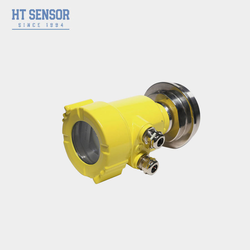
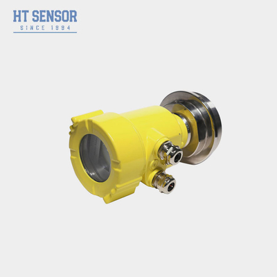
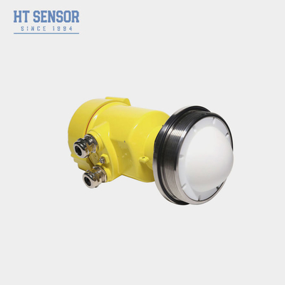
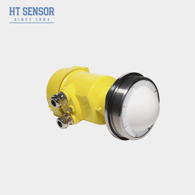
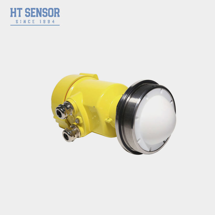
80G radar level meter
Production indroduce :
The 76-81GHz Frequency Modulated Continuous Wave (FMCW) radar products support both four-wire and two-wire applications. With multiple models, the maximum range can reach 120m, and the blind spot is as small as 10 cm. Due to its higher operating frequency and shorter wavelength, it is particularly suitable for solid applications. By emitting and receiving electromagnetic waves through a lens, it offers unique advantages in high dust and harsh temperature environments (up to +200℃). The instrument provides flange or threaded mounting options, making installation simple and convenient.
Advantages :
Based on the self-developed CMOS millimeter wave RF chip, a more compact RF architecture, higher SNR and smaller blind zone are realized.
The 5GHz working bandwidth enables the product to have higher measurement resolution and measurement accuracy.
The narrowest antenna beam Angle is 3°, the interference in the installation environment has less impact on the instrument, and the installation is more convenient.
The shorter wavelength has better reflection characteristics on the solid surface, so it does not need to use a special universal flange for aiming.
Supports mobile phone Bluetooth debugging to facilitate maintenance work of field personnel.
Technical :

Installation:
There are two points to pay attention to in installation: aim at the target material level and try to ensure vertical incidence of the material level; avoid false echo. See the following typical working conditions.
Ensure that there are no obstructions within the beam range, such as ladders and steps.

Schematic diagram of instrument installation position
The instrument should be installed at least 20cm away from the container wall, otherwise it is likely to produce incorrect readings
 Install at least 20cm from the container wall
The installation of the instrument should ensure that the antenna beam avoids the feed port, as shown in the figure
 Antenna beam avoids feed port
The conical container should ensure that the beam is directly directed to the bottom of the tank, otherwise the measurement results at the bottom of the tank may be inaccurate

The conical tank should ensure that the beam is directly directed to the bottom of the tank
Product wiring
Wiring diagram of two-wire products with single-chamber housing and 24VDC power supply

Schematic diagram of two-wire products
Wiring diagram of single-chamber housing with 24VDC power supply (4-20mA) four-wire product

In the application of four-wire system, in addition to the 24v power supply terminal, 4-20mA analog is a separate two terminals
Wiring diagram of single-chamber housing with 24VDC power supply (RS485) and four-wire products

In the application of four-wire system, in addition to the 24v power supply terminal, RS485 analog is a separate two terminals
Wiring diagram of a two-chamber shell with 220V AC power supply (4-20mA) and four-wire products

In the application of four-wire system, when 4-20mA is not output, 3 and 4 are shorted

 Your message must be between 20-3,000 characters!
 Please check your E-mail!
  Your message must be between 20-3,000 characters!
 Please check your E-mail!

